Once a developer starts working with sensors he often learns one hard fact: sensors are a tricky thing to use. They are noisy, inaccurate and easily influenced. Naturally, a question occurs: how do you filter out all the noise from the sensor and end up with the data you can actually trust and use? For this purpose, various filtering methods are employed. We will take a look at one of these. By the vast masses of the internet, it is known by the mysterious name of “Complementary filter”.
LET’S START WITH THE SENSORS.
There is a lot of various sensors. For the scope of this article, we will only bother ourselves with the ones people encounter on the everyday basis on their smartphones. Namely: accelerometer, gyroscope (gyrometer) and compass (magnetometer).
Accelerometer is a relatively fast sensor. And it’s also quite an accurate and reliable beastie. You can measure various things with it: acceleration, gravity direction, force being applied. In the smartphone world, it is often employed to detect the rotations of the device (think switching between portrait and landscape modes). But the problem with the accelerometer is that it is really susceptible to outside forces: if you don’t hold the device perfectly still and give it the slightest of nudges, this will be registered as an accelerating force, introducing noise and in process confusing calculations. For example: which direction is the gravity acting upon.
Magnetometer is actually on of the slower sensors (especially the case with the older models), but really reliable. It can be used to measure magnetic forces acting upon the device. One can even measure the magnetic force of the earth which can be used to detect the north. This, in turn, gives the ability for the device to know it’s heading position. In addition, this sensor does not suffer from noisiness. But there is a caveat still: any other magnetic force in the vicinity of the sensor and magnetometer goes haywire. And guess what: we live in the world of electricity and ferromagnetic metals. So you only need to get close enough to the wire with running electricity (even the headphone wire running from the audio jack might do) and the previous reliable readings are no good anymore. In this case at least smartphone magnetometer sensors are fair enough to provide you the current reading reliability rating.
Gyrometer, on the other hand, is a completely different sensor: it is fast, incredibly accurate and does not suffer from any outside forces. It measures the angular velocity of the device at any given moment. To get the current positioning of the device you integrate the angular velocity over time. And herein lies the problem of the gyroscope. It is susceptible to phenomena known as a gyro drift. Since you integrate with the velocity of that particular moment you are doing it on the pretense that it was constant between two gyro reads. This introduces bias. Also in the nature of it you cannot get the starting or “reliable current” position from gyro alone so, in the end, the gyrometer is not reliable in the long run.
To sum things up:
| Sensor | Fast | Reliable in the long run | Noiseless | Not influenced by outside factors |
| Accelerometer | X | X | ||
| Magnetometer | X | (+/-)* | ||
| Gyrometer | X | X | X |
*Author was really pleasantly surprised by the compass on Windows Phone
NOISE CANCELING THEORY
The solution to these problems is using the “best of both worlds”: using a fast and not influenced sensor in the short term and a noisy but reliable sensor in long run. So for example to get the tilt of the device you would use the 6 degrees of freedom provided by accelerometer (3) and gyroscope (3) to filter out the sudden movements and gyro drift.
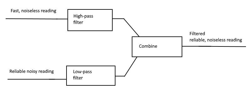
There are two main methods used to accomplish this: Kalman filter or Complementary filter. In the end, they do the same thing: combine many sensors that complement each other’s weaknesses (hence complementary) with their strengths. We will not talk about Kalman filter through, because it is really complex. It takes into account a full mathematical model of the system: taking in mass, inertias of parts of the system, etc. This means it is hard to implement and might get performance critical since a lot of data processing is involved. The Complementary filter, on the other hand, takes in the “fast reading”, runs it through HPF (high-pass filter) and adds to the reliable reading that was run through LPF (low-pass filter) in the end providing user with clean reading one can trust

IMPLEMENTATION
The implementation of Complementary filter in its essence is pretty simplistic:

this code line allows you to react on fast accurate changes but still anchors onto reliable sensor readings. The coefficients should be adjusted to conform to the needs of the application.
In the case of the noisy sensor it is still recommended to further filter out extremities. When using accelerometer + gyrometer combination for calculations, huge differences in accelerating force (like a strong shake on the device) can really skew the data. So it is advisable to leave out the accelerometer part if the force projection exceeds a certain threshold. This is not necessary in the case of compass + gyrometer combination though. With this in mind the full modified algorithm might look something like this:
private double FilterSensor(double fastReading, double reliableReading,
                            double dTime,double currentAngle, AccelerometerReading reading = null)
{
    var updatedAngle = currentAngle + fastReading * dTime;
    var forceMagnitude = 0.0;
    if (reading != null)
        forceMagnitude = Math.Abs(reading.AccelerationX) + Math.Abs(reading.AccelerationY) + Math.Abs(reading.AccelerationZ);

    if ((forceMagnitude > 0.2 && forceMagnitude < 1.7) || reading == null)
    {
        // Turning around the X axis results in a vector on the Y-axis
        updatedAngle = updatedAngle * 0.98 + reliableReading * 0.02;
    }

    return updatedAngle;
}
The algorithm takes in:
- fast unreliable reading (f.e. accelerometer)
- reliable reading (gyrometer)
- time delta between the two calls to integrate the fast reading upon
- the current angle (the one that was calculated in the previous iteration or the starting value if there were no previous iterations)
- an optional accelerometer reading that if present will try to detect and filter out accelerometer spikes in the reliable reading
…and comes out with a clean reliable value.
RESULTS
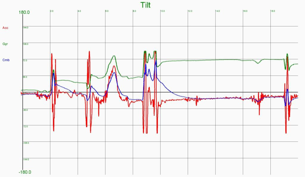
When the complimentary filter is employed and we graph out the readings from pure sensors and the combined one we can immediately see the benefits of using a complementary filter:
Notice how the combined line closely follows the fast bumps in the gyrometer sensor but still drifts towards the reliable accelerometer sensor over time.

The heading readings look a lot more stable as the magnetometer is not as noisy a sensor. The combined graph tells the familiar story as the graph before. Also, notice the clearly visible gyro drift happening over time.

CONCLUSION
As you have seen in the article every sensor even the noisiest one can be used if you employ a little bit of help from the filters. The trick is often just using the right combination of them so they can complement each other’s weaknesses. And, to reiterate, a really good way to combine them is the complementary filter as it is easy to understand and implement, not taxing on the processor and supplies you with a nice trustworthy data in the end.

